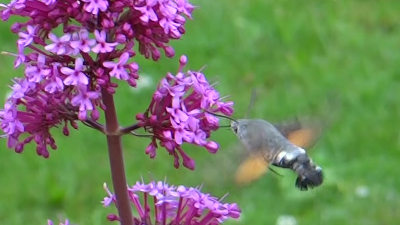
Over on one of my other blogs I recently wrote a post about a Hummingbird Hawk-Moth which I'd seen in the garden. This post included an animated GIF of the moth in flight. I included an animated GIF rather than a normal video because I'd had problems with the camera and the longest video I manged to shoot before the moth flew away contained just 14 frames.
As you can see it finishes almost before you've had chance to realise it's started to play and isn't very helpful at showing why the moth is named after the Hummingbird.
Now I'm sure there are many ways in which you could turn the video into a looping GIF but I'm going to detail what I did, partly so I don't forget, and partly as I wrote some software to deal with one particular issue.
My approach to almost any video related task usually starts with FFmpeg and this was no different, with a simple command to scale the video down and produce a GIF as output making sure to keep the right frame rate.
As you can see this works to produce an animated GIF although there are a number of problems with it. Firstly it's very grainy and secondly you can't really see the moth now we've scaled the image down. We'll deal with the second problem first (as the first problem mostly goes away by the end). Again a simple FFmpeg command allows us to crop the video:
This gives us a much better view of the moth but that jump as the animation loops around is very very annoying. The problem is that even with just 14 frames there is enough camera movement between the first and last frame for the join to be really obvious. This is something you often see with animated GIFs produced from video and you can clearly see why in this image of the first and last frames superimposed on one another.
At this point I tried a number of filters in FFmpeg that are supposed to help remove camera shake etc. but none of them helped as the camera movement is fairly smooth and what I want is to just remove the movement altogether so that the plant stay stills between the frames. While I couldn't find anyway of doing this in FFmpeg I did realise that some of the code I used in 3DAssembler might help.
I've never really described how 3DAssembler works, but essentially it aligns images. In fact it uses SURF to detect identical features in a pair of images and then determines the horizontal and vertical shift required to try and overlap as many of the features it found as possible. In 3DAssembler this allows you to automatically align photos to produce a usable stereo pair. Here though we can use the same approach to align the frames of the video.
The code I wrote (which is currently a mess of hard coded values, so I'll release it once I've had time to clean it up) calculates the horizontal and vertical shifts of each frame against the first frame and then crops each frame appropriately. If we superimpose the first and last of these corrected frames we can see how things have improved.
Producing the final animated GIF is then a multistage process. Firstly we use FFmpeg to turn the video into a series of still images, taking care to deinterlace the original video:
My code then aligns, crops, and scales these frames down to the same size we were using before. The set of frames is then reassembled to produce the animated GIF:
convert -delay 4 frame*.png animated.gif
While there is still a jump of the background as it loops around it is a lot less obvious than in the original. You'll also notice that the grain present in the original has disappeared. The grain is actually dithering introduced to try and improve the image due to the fact that a GIF image is limited to just 256 colours. I didn't apply a dither filter when assembling the GIF which does mean you can see problems with the colour palette especially in the grass at the bottom left.
I'm not sure why GIF has such a limited colour pallette but I'm guessing it relates to keeping the filesize down when storage was more expensive and bandwidth was a lot lower. Now that most peoples internet connection can handle full resolution HD video we shuold probably move beyond GIF images. For single images, especially hand drawn or those that use transparency, GIF has been replaced by PNG. The PNG format also supports animation. Unfortunately only Firefox currently has support for showing animated PNG images, in all the other browsers all you see is the first frame.
Fortunately it is possible to get animated PNGs to play in most modern browsers with a little bit of JavaScript trickery using the apng-canvas library. Unfortunately the way this library works means that you need to host both the image and the javascript in the same place which makes it difficult to use with blogger, not helped by the fact the you can't currently upload animated PNG files to blogger either. Anyway after a little bit of work hopefully the following should be animated for everyone.
As you can see this is much better than the GIF version as we aren't limited to just 256 colours. This was produced in exactly the same way as the GIF version though, apart from the final command to assemble the file which now looks like:
apngasm animated.png frame*.png 1 25
I'll clean up the code I used and make it available in case anyone else fancies producing weird little animated videos.
I really hoped I was done writing posts about how Blogger was messing with our blogs, but unfortunately here I am writing another post. It seems that something in the way images are added to our posts has changed and this in turn means that Blogger no longer generates and includes a thumbnail for each post in the feeds produced for a blog. Whilst this doesn't effect the look of your blog it will make it look less interesting when viewed in a feed reader or blog list on another blog as only the title of the posts will appear.
The problem appears to be that when you upload and embed an image, for some reason Blogger is omitting the http: from the beginning of the image URL. This means that all the image URLs now start with just //. This is perfectly valid (it's defined in RFC 1808) and is often referred to as a scheme relative URL. What this means is that the URL is resolved relative to the scheme (http, https, ftp, file, etc.) of the page in which it is embedded.
I'm guessing this changes means that blogger is looking at switching some blogs to be served over https instead of http. Leaving the scheme off the image URL means that the image will be served using the same scheme as the page regardless of what that is. The problem though is that the code that blogger uses to generate the post feeds seem to ignore images that don't start http: meaning that no thumbnails are generated.
For now the easy fix is to manually add the http: to the image URLs (or at least of the image you want to use as the thumbnail for the post). Of course it would be better if blogger just fixed their code to spot these URLs properly and include them in the post feed.
Updated 18th November 2014: It looks as if this problem has been resolved as I've just tried posting on one of my other blogs and the http: bit is back.
In the very abstract sense text analysis can be divided into three main tasks; load some text, process it, export the result. Out of the box GATE (both the GUI and the API) provides excellent support for both loading documents and processing them, but until now we haven't provided many options when it comes to exporting processed documents.
Traditionally GATE has provided two methods of exporting processed documents; a lossless XML format that can be reloaded into GATE but is rather verbose, or the "save preserving format" option which essentially outputs XML representing the original document (i.e. the annotations in the Original markups set) plus the annotations generated by your application. Neither of these options were particularly useful if you wanted to pass the output on to some other process and, without a standard export API, this left people having to write custom processing resources just to export their results.
To try and improve the support for exporting documents recent nightly builds of GATE now include a common export API in the gate.DocumentExporter class. Before we go any further it is worth mentioning that this code is in a nightly build so is subject to change before the next release of GATE. Having said that I have now used it to implement exporters for a number of different formats so I don't expect the API to change drastically.
If you are a GATE user, rather than a software developer, than all you need to know is that an exporter is very similar to the existing idea of document formats. This means that they are CREOLE resources and so new exporters are made available by loading a plugin. Once an exporter has been loaded then it will be added to the "Save as..." menu of both documents and corpora and by default exporters for GATE XML and Inline XML (i.e. the old "Save preserving format) are provided even when no plugins have been loaded.
If you are a developer and wanting to make use of an existing exporter, then hopefully the API should be easy to use. For example, to get hold of the exporter for GATE XML and to write a document to a file the following two lines will suffice:
There is also a three argument form of the export method that takes a FeatureMap that can be used to configure an exporter. For example, the annotation types the Inline XML exporter saves is configured this way. The possible configuration options for an exporter should be contained in it's documentation, but possibly the easiest way to see how it can be configured is to try it from the GUI.
If you are a developer and want to add a new export format to GATE, then this is fairly straightforward; if you already know how to produce other GATE resources then it should be really easy. Essentially you need to extend gate.DocumentExporter to provide an implementation of it's one abstract method. A simple example showing an exporter for GATE XML is given below:
@CreoleResource(name = "GATE XML Exporter",
   tool = true, autoinstances = @AutoInstance, icon = "GATEXML")
public class GateXMLExporter extends DocumentExporter {

  public GateXMLExporter() {
    super("GATE XML", "xml", "text/xml");
  }

  public void export(Document doc, OutputStream out, FeatureMap options)
          throws IOException {
    try {
      DocumentStaxUtils.writeDocument(doc, out, "");
    } catch(XMLStreamException e) {
      throw new IOException(e);
    }
  }
}
As I said earlier this API is still a work in progress and won't be frozen until the next release of GATE, but the current nightly build now contains export support for Fast Infoset compressed XML (I've talked about this before), JSON inspired by the format Twitter uses, and HTML5 Microdata (an updated version of the code I discussed before). A number of other exporters are also under development and will hopefully be made available shortly.
Hopefully if you use GATE you will find this new support useful and please do let us have any feedback you might have so we can improve the support before the next release when the API will be frozen.
The majority of the code I write as part of my day job revolves around trying to extract useful semantic information from text. Typical examples of what is referred to as "semantic annotation" include spotting that a sequence of characters represents the name of a person, organization or location and probably then linking this to an ontology or some other knowledge source. While extracting the information can be a task in itself, usually you want to do something with the information often to enrich or make the original text document more accessible in some way. In the applications we develop this usually entails indexing the document along with the semantic annotations to allow for a richer search experiance and I've blogged about this approach before. Such an approach assumes, however, that the consumer of the semantic annotations will be a human, but what if another computer programme wants to make use of the information we have just extracted. The answer is to use some form of common machine readable encoding.
While there is already an awful lot of text in the world, more and more is being produced everyday, usually in electronic form, and usually published on the internet. Given that we could never read all this text we rely on search engines, such as Google, to help us pinpoint useful or interesting documents. These search engines rely on two main things to find the documents we are interested in, the text and the links between the documents, but what if we could tell them what some of the text actually means?
In the newest version of the HTML specification (which is a work in progress usually referred to as HTML5) web pages can contain semantic information encoded as HTML Microdata. I'm not going to go into the details of how this works as there is already a number of great descriptions available, including this one.
HTML5 Microdata is, in essence, a way of embedding semantic information in a web page, but it doesn't tell a human or a machine what any of the information means, especially as different people could embed the same information using different identifiers or in different ways. What is needed is a common vocabulary that can be used to embed information about common concepts, and currently many of the major search engines have settled on using schema.org as the common vocabulary.
When I first heard about schema.org, back in 2011, I thought it was a great idea, and wrote some code that could be used to embed the output of a GATE application within a HTML page as microdata. Unfortunately the approach I adopted was, to put it bluntly, hacky. So while I had proved it was possible the code was left to rot in a dark corner of my SVN repository.
I was recently reminded of HTML5 microdata and schema.org in particular when one of my colleges tweeted a link to this interesting article. In response I was daft enough to admit that I had some code that would allow people to automatically embed the relevant microdata into existing web pages. It wasn't long before I'd had a number of people making it clear that they would be interested in me finishing and releasing the code.
I'm currently in a hotel in London as I'm due to teach a two day GATE course starting tomorrow (if you want to learn all about GATE then you might be interested in our week long course to be held in Sheffield in June) and rather than watching TV or having a drink in the bar I thought I'd make a start on tidying up the code I started on almost three years ago.
Before we go any further I should point out that while the code works the current interface isn't the most user friendly. As such I've not added this to the main GATE distribution as yet. I'm hopping that any of you who give it a try can leave me feedback so I can finish cleaning things up and integrate it properly. Having said that here is what I have so far...
I find that worked examples usually help convey my ideas better than prose so, lets start with a simple HTML page:
<html>
  <head>
    <title>This is a schema.org test document</title>
  </head>
  <body>
    <h1>This is a schema.org test document</h1>
    <p>
      Mark Greenwood works in Sheffield for the University of Sheffield.
      He is currently in a Premier Inn in London, killing time by working on a GATE plugin to allow annotations to be embedded within a HTML document using HTML microdata and the schema.org model.
    </p>
  </body>
</html>
As you can see this contains a number of obvious entities (people, organizations and locations) that could be described using the schema.org vocabulary (people, organizations and locations are just some of the schema.org concepts) and which would be found by simply running ANNIE over the document.
Once we have sensible annotations for such a document, probably from running ANNIE, and a mapping between the annotations and their features and the schema.org vocabulary then it is fairly easy to produce a version of this HTML document with the annotations embedded as microdata. The current version of my code generate the following file:
<html>
  <head>
    <title>This is a schema.org test document</title>
  </head>
  <body>
    <h1>This is a schema.org test document</h1>
    <p>
      <span itemscope="itemscope" itemtype="http://schema.org/Person"><meta content="male" itemprop="gender"/><meta content="Mark Greenwood" itemprop="name"/>Mark Greenwood</span> works in <span itemscope="itemscope" itemtype="http://schema.org/City"><meta content="Sheffield" itemprop="name"/>Sheffield</span> for the <span itemscope="itemscope" itemtype="http://schema.org/Organization"><meta content="University of Sheffield" itemprop="name"/>University of Sheffield</span>.
      He is currently in a <span itemscope="itemscope" itemtype="http://schema.org/Organization"><meta content="Premier" itemprop="name"/>Premier</span> Inn in <span itemscope="itemscope" itemtype="http://schema.org/City"><meta content="London" itemprop="name"/>London</span>, killing time by working on a GATE plugin to allow <span itemscope="itemscope" itemtype="http://schema.org/Person"><meta content="female" itemprop="gender"/><meta content="ANNIE" itemprop="name"/>ANNIE</span> annotations to be embedded within a HTML document using HTML microdata and the schema.org model.
    </p>
  </body>
</html>
This works nicely and the embeded data can be extracted by the search engines, as proved using the Google rich snippets tool.
As I said earlier while the code works, the current integration with the rest of GATE definitely needs improving. If you load the plugin (details below) then right clicking on a document will allow you to Export as HTML5 Microdata... but it won't allow you to customize the mapping between annotations and a vocabulary. Currently the ANNIE annotations are mapped to the schema.org vocabulary using a config file in the resources folder. If you want to change the mapping you have to change this file. In the future I plan to add some form of editor (or at least the ability to choose a different file) as well as the ability to export a corpus not just a single file.
So if you have got all the way to here then you probably want to get your hands on the current plugin, so here it is. Simply load it into GATE in the usual way and it will add the right-click menu option to documents (you'll need to use a nightly build of GATE, or a recent SVN checkout, as it uses the resource helpers that haven't yet made it into a release version).
Hopefully you'll find it useful but please do let me know what you think, and if you have any suggestions for improvements, especially around the integration the GATE Developer GUI.
At work we are slowly getting ready for a major new release of GATE. In preparation for the release I've been doing a bit of code cleanup and upgrading some of the libraries that we use. After every change I've been running the test suite and unfortunately some of the tests would intermittently fail. Given that none of the other members of the team had reported failing tests and that they were always running successfully on our Jenkins build server I decided the problem must be something related to my computer. My solution then was simply to ignore the failing tests as long as they weren't relevant to the code I was working on, and then have the build server do the final test for me. This worked, but it was exceedingly frustrating that I couldn't track down the problem. Yesterday I couldn't ignore the problem any longer because the same tests suddenly started to randomly fail on the build server as well as my computer and so I set about investigating the problem.
The tests in question are all part of a single standard JUnit test suite that was originally written back in 2001 and which have been running perfectly ever since. Essentially these tests run the main ANNIE components over four test documents checking the result at each stage. Each component is checked in a different test within the suite. Now if you know anything about unit testing you can probably already hear alarm bells ringing. For those of you that don't know what unit testing is, essentially each test should check a single component of the system (i.e. a unit) and should be independent from every other test. In this instance while each test checked a separate component, each relied on all the previous tests in the suite having run successfully.
Now while dependencies between tests isn't ideal it still doesn't explain why they should have worked fine for twelve years but were now failing. And why did they start failing on the build server long after they had been failing on my machine. I eventually tracked the change that caused them to fail when run on the build server back to the upgrade from version 4.10 to 4.11 of JUnit but even with the help of a web search I couldn't figure out what the problem was.
Given that I'd looked at the test results from my machine so many times and not spotted any problems I roped in some colleagues to run the tests for me on their own machines and send me the results to see if I could spot a pattern. The first thing that was obvious was that when using version 4.10 of JUnit the tests only failed for those people running Java 7. GATE only requires Java 6 and those people still with a Java 6 install, which includes the build server (so that we don't accidentally introduce any Java 7 dependencies), were not seeing any failures. If, however, we upgraded JUnit to version 4.11 everyone started to see random failures. The other thing that I eventually spotted was that when the tests failed, the logs seemed to suggest that they had been run in a random order which, given the unfortunate links between the tests, would explain why they then failed. Armed with all this extra information I went back to searching the web and this time I was able to find the problem and an easy solution.
Given that unit tests are meant to be independent from one another, there isn't actually anything within the test suite that stipulates the order in which they should run, but it seems that it always used to be the case that the tests were run in the order in which they were defined in the source code. The tests are extracted from the suite by looking for all methods that start with the word test, and these are extracted from the class definition using the Method[] getDeclaredMethods() method from java.lang.Class. The documentation for this method includes the following description:
Returns an array of Method objects reflecting all the methods declared by the class or interface represented by this Class object. This includes public, protected, default (package) access, and private methods, but excludes inherited methods. The elements in the array returned are not sorted and are not in any particular order.
This makes it more than clear that we should never have assumed that the tests would be run in the same order they were defined, but it turns out that this was the order in which the methods were returned when using the Sun/Oracle versions of Java up to and including Java 6 (update 30 is the last version I've tested). I've written the following simple piece of code that shows the order of the extracted tests as well as info on the version of Java being used:
import java.lang.reflect.Method;

public class AtSixesAndSevens {
  public static void main(String args[]) {
    System.out.println("java version \"" +
      System.getProperty("java.version") + "\"");
    System.out.println(System.getProperty("java.runtime.name") +
      " (build " + System.getProperty("java.runtime.version") + ")");
    System.out.println(System.getProperty("java.vm.name") +
      " (build " + System.getProperty("java.vm.version") + " " +
      System.getProperty("java.vm.info") + ")\n");

    for(Method m : AtSixesAndSevens.class.getDeclaredMethods()) {
      if(m.getName().startsWith("test"))
        System.out.println(m.getName());
    }
  }

  public void testTokenizer() {}
  public void testGazetteer() {}
  public void testSplitter() {}
  public void testTagger() {}
  public void testTransducer() {}
  public void testCustomConstraintDefs() {}
  public void testOrthomatcher() {}
  public void testAllPR() {}
}
Running this on the build server gives the following output:
java version "1.6.0_26"
Java(TM) SE Runtime Environment (build 1.6.0_26-b03)
Java HotSpot(TM) 64-Bit Server VM (build 20.1-b02 mixed mode)

testTokenizer
testGazetteer
testSplitter
testTagger
testTransducer
testCustomConstraintDefs
testOrthomatcher
testAllPR
While running it on my machine results in a random ordering of the test methods as you can see here:
java version "1.7.0_51"
OpenJDK Runtime Environment (build 1.7.0_51-b00)
OpenJDK 64-Bit Server VM (build 24.45-b08 mixed mode)

testTagger
testTransducer
testGazetteer
testSplitter
testTokenizer
testCustomConstraintDefs
testOrthomatcher
testAllPR
Interestingly it would seem that the order only changes when the class is re-compiled, which suggests that the ordering may be related to how the methods are stored in the class file, but understanding the inner workings of the class file format is well beyond me. Even more interestingly it seems that even with Java 6 you can see a random ordering if you aren't using a distribution from Sun/Oracle, as here is the output from running under the Java 6 version of OpenJDK:
java version "1.6.0_30"
OpenJDK Runtime Environment (build 1.6.0_30-b30)
OpenJDK 64-Bit Server VM (build 23.25-b01 mixed mode)

testTagger
testTransducer
testCustomConstraintDefs
testOrthomatcher
testAllPR
testTokenizer
testGazetteer
testSplitter
So this explains why switching from Java 6 to Java 7 could easily cause these related tests to fail, but why should upgrading from JUnit version 4.10 to 4.11 while staying with Java 6 cause a problem?
It turns out that in the new version of JUnit the developers decided to change the default behaviour away from relying on the non-deterministic method ordering provided by Java. Their default approach is now to use a deterministic ordering to guarantee the tests are always run in the same order; as far as I can tell this orders the methods by sorting on the hashCodes of the method names. While this may at least remove the randomness from the test order it doesn't keep them in the same order they are defined in the source file, and so our tests were always failing under JUnit 4.11. Fortunately the developers also allow you to add a class level annotation to force the methods to be ordered alphabetically. I've now renamed the tests so that when sorted alphabetically they are run in the right order (by adding a three digit number after the initial test in their name), and the class definition now looks like:
@FixMethodOrder(MethodSorters.NAME_ASCENDING)
public class TestPR extends TestCase {
  ...
}
So I guess there are two morals to this story. Firstly unit tests are called unit tests for a reason and they really should be independent of one another, but more importantly reading the documentation for the language or library you are using and not making assumptions about how they work (especially when the documentation tells you not to rely on something always being true) would make life easier.
Now before you all get confused this isn't a post about health or beauty tips for your thumbnails, but rather about a little trick I sometimes use to improve the thumbnails Blogger generates for each post.
When you publish a post through Blogger not only does the post appear on your blog but Blogger also inserts the content into two news feeds (RSS and Atom formats) which people can subscribe to in order to know when you have published something new. These feeds are also used to fill in the blog list widget that many people include in their blog template; you can see mine under the heading "I'm Also..." on the right.
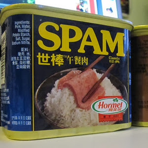
If you have included an image in your post, and the image is hosted by Blogger (i.e. has blogspot in the URL) then as well as putting the post content into the news feed Blogger will generate a small thumbnail to represent the post. It appears to do this by creating a 72 pixel square thumbnail from the first image in the post. Specifically it scales the image so that the short edge is 72 pixels long and then crops the other dimension to retain the middle of the image. You can see this working with the image of a Chinese tin of spam from one of my recent posts.
To make the images easier to see I've used a width of the 300 pixels instead of 72 but the result is the same. On the left you can see the original image sized to 300 pixels wide, whereas on the right we have a 300 pixel thumbnail generated by scaling the height first and then cropping the width. In this example the cropping isn't too bad as it has retained almost all of the important content, but you can easily imagine images where the cropping could result in thumbnails that were far from ideal; chopping off peoples heads is a common example.
Fortunately it is easy to control the thumbnail that is generated by ensuring that the first image in your post is already square and cropped to your satisfaction. Now of course that would often leave you with an image you don't actually want to use, but that is alright as my trick doesn't actually result in the image appearing in the post anyway.
To customize the thumbnail all you have to do is upload the square image you want to use (it can be any size although as it will always be displayed as a 72 pixel square there isn't much point making it too big) through the Blogger interface and then switch to the HTML editor view. Now we don't need all the HTML that Blogger generates as all we need is the img tag. So you can remove everything surround the image and move the rest to the very beginning of your post. So for this post that looks something like (I've trimmed the URL to fit the screen):
By placing this at the beginning of the post we ensure that this image is the one Blogger uses when it generates the thumbnail, and we can hide it for all other purposes by adding some CSS to the image as follows:
In this case the CSS is fairly self-explanatory as it simply turns off the display of the image. And that is it, a very simple trick but one that can make your blog look better in other peoples news feeds.
As well as using this to customize a thumbnail that Blogger would already generate you can of course use it to generate thumbnails in cases where Blogger otherwise wouldn't. The two main cases where this might be useful are firstly where you host your images somewhere else (maybe flicker) or, and this is where I most often use this trick, if you have embedded a YouTube video instead of an image in your post. In neither case does Blogger generate a thumbnail for you, but you should be able to see how easy it would be to add your own.
I've recently been building a simple proof-of-concept web application which may or may not see the light of day, but essentially it builds an SVG image directly within the browser through user interaction. One useful feature would be to allow the user to download the completed SVG file (as a backup or for use elsewhere). After quite a bit of experimentation with some of the newer HTML features I now have a (mostly) working solution, which I've reduced down to a simple example using the Kiwi to the left (the SVG for this image comes from a useful tutorial by Chris Coyier). If you can't see a Kiwi then your browser doesn't supporting displaying SVG images and certainly won't support the techniques in the rest of this post, so if you want to follow along you'll need to find a more modern browser.
Given that the SVG image is being built through standard DOM manipulation it is easy to get the text of the SVG file directly via JavaScript. For example, if we assume that the SVG element has the id svg then the following will get the full text of the image.
// get a copy of the DOM element with the id "svg"
var svg = document.getElementById("svg").cloneNode();

// get the text of this element, including the element and all children
var content = svg.outerHTML;

if (content == undefined) {
  // if there is no content then the outerHTML property isn't supported...

  // so create a new DIV element
  var div = document.createElement("div");

  // append the SVG to the DIV
  div.appendChild(svg);

  // use the widely supported innerHTML to get at the text of the SVG
  content = div.innerHTML;
}
This is a little more convoluted than I would like due to the fact that while all browsers support outerHTML not all of them (specifically Chrome) support it on the SVG element. Either way this code allows us to get the text we need to return as an SVG file to the user. Note that I've cloned the SVG node (line 2) rather than just referencing it directly, because changing a nodes parent in Chrome causes it to disappear from the document, which clearly isn't what we want. The more complex part of the problem then is figuring out how to return the text as an SVG to the user.
Given that I was looking at this in the context of a large web application, probably the easiest option would have been to send the text back to the server, which could then return it to the browser with a sensible filename and mime type (image/svg+xml), but this would clearly be rather inefficient, especially as the SVG image grows in size. It would also preclude the technique from being used in simple client side applications which didn't use a web server.
I stumbled upon an almost working example by accident. It turns out that if you simply return the SVG data from within a JavaScript href link the SVG will open within the browser, allowing the user to simply save the page to download the SVG. So we can wrap up the code above in a function:
function saveAsSVG(id) {
  var svg = document.getElementById(id).cloneNode();

  var content = svg.outerHTML;

  if (content == undefined) {
    var div = document.createElement("div");
    div.appendChild(svg);
    content = div.innerHTML;
  }

  return content;
}
And you can see what happens with this live version of the above. If you've just tried that you will have hopefully noticed a few problems:
the image is missing all it's colour information (the kiwi and grass are both black)
when you save the image the browser suggests a HTML filename
the file you save is actually a HTML file not an SVG as the browser adds some extra HTML wrapping
While these are all clearly problems I was encouraged that I was at least heading in roughly the right direction. The missing colours I had expected (and will come back to later) and so I focused on the final two related problems first. After searching the web I came across the HTML5 download attribute that the specification seemed to suggest was exactly what I needed. Essentially the new download attribute, when applied to a link, signals to the browser that the item the link points to should be downloaded rather than display. It also allows you to specify a filename that the browser should suggest when the user clicks the link. So using this with the above gets us:
which again you can try for your self with this live version of the above. Now I don't know which browser you are using, but I was developing this in Firefox, and I was amazed to find that this works; clicking the link pops up a "save as" dialog with the correct file name and the saved file is the correct SVG file. Unfortunately trying the same thing in both Opera and Chrome doesn't work. In Opera, the attribute seems to be simply ignored as it doesn't change the behaviour, while in Chrome when you click the link nothing happens, and no errors are reported. As far as Opera is concerned the problem seems to be that I'm running the latest version available for Ubuntu which is v12, while the most recent version for Windows and Mac is 18; so if Opera are abandoning Linux I'm going to abandon testing with Opera.
Now while I could mandate specific browser versions for the app I was working on I really did want to try and find a more general solution. Also I had noticed that even once you have saved the SVG in Firefox the throbber never stops spinning, which usually suggests that the browser isn't really happy with what you have just done! Fortunately the search that led me to the download attribute also pointed me at a related new HTML feature; the blob.
A blob"represents a file-like object of immutable, raw data. Blobs represent data that isn't necessarily in a JavaScript-native format", which sounds like exactly what I need, especially as a blob can be referenced by a URL. I'm not going to detail all the possible features or ways of using blobs, but the following single line of code can be used to create a blob from the SVG content we already know how to extract:
var blob = new Blob([content], {type: "image/svg+xml"});
If you remember from before the variable content holds the text of the SVG file we want to create, so this line creates a binary blob from the SVG data with the right mime type. It is also easy to create and destroy URLs that point to these blobs. For example, the following creates and then immediately destroys a URL pointing to the blob.
var url = window.URL.createObjectURL(blob);
window.URL.revokeObjectURL(url);
You can probably get away without explicitly revoking every URL you create as they should be automatically revoked when the page is unloaded, but it is certainly a good idea to release them if you know that a) the URL is invalid and b) you are creating a lot of these URLs. One thing to note is that Chrome (and other WebKit based browsers) use a vendor prefix for the URL object (i.e. it's called webkitURL) so we need to make sure that regardless of the browser we are using we can access the functions we need. Fortunately this is easy to do by adding the following line (outside of any function):
window.URL = window.URL || window.webkitURL;
So the remaining question is how do we string all these bits together so that clicking a link on a page, builds a blob, generates a URL and then allows the user to download the URL. All the solutions I saw while searching the web did this in two steps. Essentially they had a link or button that when clicked would build the blob, generate the URL, and then add a new link to the document. This new link would use the download attribute and the blob URL to allow the user to download the file. While this works it doesn't seem particularly user friendly. Fortunately it is easy to combine all this functionality into a single link.
The trick to doing everything within a single link is to use the onclick event handler of the link to build the blob and generate the URL which it then sets as the href attribute of the link. As long as the onclick event handler returns true then the browser will follow the href which now points at the blob URL and when we combine this with the download attribute the result is that the user is prompted to download the blob. So the function I came up with looks like the following:
function saveAsSVG(id, link) {

  if (link.href != "#") {
    window.URL.revokeObjectURL(link.href);
  }

  var svg = document.getElementById(id).cloneNode();

  var content = svg.outerHTML;

  if (content == undefined) {
    var div = document.createElement("div");
    div.appendChild(svg);
    content = div.innerHTML;
  }

  var blob = new Blob([content], {type: "image/svg+xml"});

  link.href = window.URL.createObjectURL(blob);

  return true;
}
Essentially this is just all the code we have already seen assembled into a single function, although it assumes that the initial href is # so that it doesn't try and revoke an invalid URL (from testing it seems that trying to revoke something that isn't valid is simply ignored, but this is slightly safer). We can then call this function from a link as follows:
And again you can try this for yourself using this live version of the above. Now this should work in all browsers that support these new HTML features which, according to the excellent Can I Use... website, should be most modern browsers. The only remaining issue is that the kiwi and grass are still both black in the downloadable SVG.
The reason the colour information is lost is that it was never part of the SVG to start with. In this example, the SVG is styled using CSS within the web page rather than directly within the SVG. When you download the SVG file you don't get the associated CSS styles and hence the elements revert back to being black. If we had used a self contained SVG image then everything would work and we would have no need to go any further. Fortunately, even when we style the SVG using CSS it is fairly easy to merge the styles into the SVG before the user downloads the image. In this example the page contains the following CSS style element.
Fortunately it is easy to add CSS styles to the SVG image before creating the blob object. If we assume that there is a function that returns a DOM style element then we can extend our existing function to embed this into the SVG as follows:
function saveAsStyledSVG(id, styles, link) {

  if (link.href != "#") {
    window.URL.revokeObjectURL(link.href);
  }

  var svg = document.getElementById(id).cloneNode();
  svg.insertBefore(getStyles(styles),svg.firstChild);

  var content = svg.outerHTML;

  if (content == undefined) {
    var div = document.createElement("div");
    div.appendChild(svg);
    content = div.innerHTML;
  }

  var blob = new Blob([content], {type: "image/svg+xml"});

  link.href = window.URL.createObjectURL(blob);

  return true;
}
Here you can see that on line 8 we call a function getStyles to get the DOM element and then append this as the first child of the root element of the SVG document, but the rest of the function is identical (other than the name as we can't overload functions in JavaScript). Now all we need to do is to define the getStyles function, which we do as follows:
function getStyles(names) {

  // create an empty style DOM element
  var styles = document.createElement("style");

  // set the type attribute to text/css
  styles.setAttribute("type","text/css");

  // get easy access to the Array slice method
  var slice = Array.prototype.slice;

  for (var i = 0 ; i < document.styleSheets.length ; ++i) {
    // for each style sheet in the document
    var sheet = document.styleSheets[i];

    if (names == undefined || names.indexOf(sheet.title) != -1) {
      // if we are including all styles or this sheet is one we want

      slice.call(document.styleSheets[i].cssRules).forEach(
        // slice the style sheet into separate rules
        function(rule){
          // create a new text node with the text of each CSS rule
          var text = document.createTextNode("\n"+rule.cssText);

          // add the rule to the style sheet we are building
          styles.appendChild(text);
        }
      );
    }
  }

  // return the completed style sheet
  return styles;
}
Hopefully the comments make it clear how this works, but essentially is finds all the rules within a named set of style sheets and adds them to a newly created style DOM element. It's worth noting that it is much safer to explicitly specify the style sheets you want to use because a) it will be quicker, b) the resultant file will be smaller but most importantly c) you can't access the content of style sheets loaded from another domain than the current page as this goes against the browser security model.
So given these new functions we can now use a link defined as follows to allow the kiwi to be downloaded in all it's glorious colours:
And again here is a live version of the above for you to try, which should allow you to download the full colour SVG.
Hopefully you have found this a useful and interesting exploration of some of the newer features of HTML, but it is worth noting that the techniques discussed could be used for downloading a whole range of different file types without requiring server interaction.
 GITHUB
 JENKINS
 DEMOS
DEMOS


 Now before you all get confused this isn't a post about health or beauty tips for your thumbnails, but rather about a little trick I sometimes use to improve the thumbnails Blogger generates for each post.
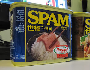
 I've recently been building a simple proof-of-concept web application which may or may not see the light of day, but essentially it builds an